Setting the element sizes
To limit the time and resources required to run finite element analysis, an adaptively sized tetrahedral volume mesh is needed, with a finer resolution mesh near wellbores and other features of interest. In the Set Element Sizes step of the Surface Meshing workflow (model > 3D Mesh > Set Element Sizes), you create a 3D definition that is visualized as an easy grid. This 3D definition is used during the surface re-triangulation and 3D mesh volume meshing.
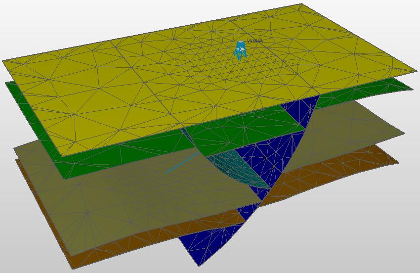
3D mesh structural model with refinement region around the wellbore. click to enlarge
You can create as complex a size definition as you require by creating as many mesh refinement regions as you wish. In case these regions are overlapping, the minimum size is used.
To set the element sizes
- On the Set Element Sizes form (model > 3D Mesh > Set Element Sizes), set the default, or 'background', element size by entering a value in the Maximum element size field under Full Mesh Parameters. (You can optionally take the full mesh parameter and mesh refinement regions from an existing 3D mesh structural model, see step 4 below.)
- A very steep element size transition at the boundaries of refinement regions may cause issues during finite element analysis, therefore you should set an acceptable value in the Gradation field. The gradation is defined as a growth factor of an edge length. If the gradation is 2, then two triangles edges that are connected may not differ more than a factor of 2. Gradation should always be greater than 1, a value between 1.5 and 2.5 is recommended. Upon opening the Set Element Sizes form, a default value of 2 is already entered.
- Under Mesh Refinement Regions, you find the options to increase the detail of the model in regions of particular interest, see Adding mesh refinement regions. As you build your size definition, you can click Apply to save your settings and Preview to visualize the mesh regions.
-
(Alternative) The Autofill button opens the Autofill form. It enables you to use the settings from another 3D mesh structural model. This includes the Full Mesh Parameter settings and the Mesh Refinement Regions settings. Any information already present on the form will be overwritten. From the model drop-down list, select the 3D mesh structural model to take the settings from. Click OK to autofill the Set Element Sizes form and close the Autofill form. Click Apply or OK at the base of the Set Element Sizes form to save the settings.
Preview
When you click Preview, you visualize the mesh refinement region(s) in a temporary grid. The name of the grid will be <name of the 3D mesh structural model>(SZ). The mesh refinement regions are highlighted (as a property of the temporary grid). Once you click OK on the Set Element Sizes form, the grid is removed from the solution again.
To add mesh refinement regions
You can add as many mesh regions as you need. If they overlap, the smallest target element size will be used.
- In the Mesh Refinement Regions section of the form, click the green plus icon (
 ) to open a drop-down list with predefined regions.
 - From the drop-down list, select Area. This updates the Regions table with an area region. Double click on the area region to change the name.
- At the right side of the form, under section Geometry, select an area from the Area drop-down list. This list will show all the areas in your solution. If you do not yet have a suitable area, you can create a new one with the Area Tool.
- Target element size Specify a value for the size of the elements inside the refinement region. The target element size must be smaller than the maximum element size.
- Click Apply to save the settings and keep the form open and continue working, or click OK to save the settings and continue with the next step in the workflow.
- In the Mesh Refinement Regions section of the form, click the green plus icon () to open a drop-down list with predefined regions.
- From the drop-down list, select Boundary. This updates the Regions table with a boundary region. Double click on the boundary region to change the name.
- At the right side of the form, under section Geometry, select the folder (either Data or Imports) from the Source drop-down list that contains the boundary you want to use as refinement area.
- Boundary Select a boundary from the drop-down list. For more information about boundaries, see Boundaries and Feature Sets.
- TOP TVDSS Specify a value for the top TVDSS of the mesh refinement region.
- Bottom TVDSS Specify a value for the bottom TVDSS of the mesh refinement region.
- Target element size Specify a value for the size of the elements inside the region you have selected. The target element size must be smaller than the maximum element size.
- Click Apply to save the settings and keep the form open and continue working, or click OK to save the settings and continue with the next step in the workflow.
- In the Mesh Refinement Regions section of the form, click the green plus icon () to open a drop-down list with predefined regions.
- From the drop-down list, select Wellbore. This updates the Regions table with a wellbore region. Double click on the wellbore region to change the name.
- At the right side of the form, under section Geometry, select a wellbore from Wellbore drop-down list.
- Radius Set a radius to determine the distance the region should extend from the wellbore.
- Top measured depth Specify a value for the top MD of the mesh refinement region.
- Bottom measured depth Specify a value for the bottom MD of the mesh refinement region.
- Target element size Specify a value for the size of the elements inside the region you have selected. The target element size must be smaller than the maximum element size.
- Click Apply to save the settings and keep the form open and continue working, or click OK to save the settings and continue with the next step in the workflow.
- In the Mesh Refinement Regions section of the form, click the green plus icon () to open a drop-down list with predefined regions.
- From the drop-down list, select Point set. This updates the Regions table with a point set region. Double click on the point set region to change the name.
- At the right side of the form, under section Geometry, select the folder (either Data or Imports) from the Source drop-down list that contains the point set you want to use as refinement area.
- Point set Select a point set from the drop-down list. The refinement region is the collection of spheres around the nodes of the point set.
- Radius Set a radius. . In between the nodes, the elements will coarsen the maximum target size controlled by the gradation. This means that if the distance between the nodes is much larger than the given radius, this coarsening is seen.
- Target element size Specify a value for the size of the elements inside the region you have selected. The target element size must be smaller than the maximum element size.
- Click Apply to save the settings and keep the form open and continue working, or click OK to save the settings and continue with the next step in the workflow.
- In the Mesh Refinement Regions section of the form, click the green plus icon () to open a drop-down list with predefined regions.
- From the drop-down list, select Surface. This updates the Regions table with a surface region. Double click on the surface region to change the name.
- At the right side of the form, under section Geometry, select a surface from the surface drop-down list that you want to use as refinement area. All the surfaces that are available for the selected 3D Mesh structural model are listed.
- Distance Fill in a value to determine the distance the region should extend from the surface.
- Target element size Specify a value for the size of the elements inside the region you have selected. The target element size must be smaller than the maximum element size.
- Click Apply to save the settings and keep the form open and continue working, or click OK to save the settings and continue with the next step in the workflow.
To remove a mesh refinement region from the table, select it in the table by clicking on it. The selected mesh refinement region is highlighted in blue. Click the  icon and click Apply.
When you need a boundary as a line (i.e. polyline, either open or closed), there are several ways to create one. Once created, polylines are stored in the Data > Boundaries folder as a polyline set (the polyline set will consist of one single polyline in this case). Whether or not a boundary needs to be closed depends on its use. You can verify whether a polyline is closed via the Polyline form (right-mouse click on a polyline set in the JewelExplorer or in a view and select Edit... ). On the form a checkbox next to the polyline's Id marks whether it is closed, or not.
Creating a boundary based on existing data
Right mouse click on a tri-mesh in the JewelExplorer or in the 2D/3D View and select Create > Create Boundary from the context menu.
Right mouse click on a constraint in the JewelExplorer, in the dedicated Thickness/Trend Map View or in the 2D/3D View and select Create > Create Boundary from the context menu.
Right mouse click on an area in the JewelExplorer or in the 2D/3D View and select Create Boundary.
Creating a boundary from scratch
To create a new boundary, click on Data in the JewelExplorer and select Create Object from the context menu. On the Create Object form, type a Name for the boundary you want to create and select Boundary from the Type drop-down list. Click OK to create the boundary and close the form. The new boundary and polyline set representation will appear in the Boundary folder inside the Data folder in the JewelExplorer, but the polyline set will be 'empty' (it does not contain any polylines yet). Next, with the polyline set selected in the JewelExplorer, open the graphical editing tools (Workspace > Tools > Editing Tools). The name of the boundary should appear in the title bar of the floating palette. In your 3D View, make sure you can see a surface on which to 'draw' the boundary. Choose from one of the following scenarios to 'draw' the line:
- Click the Add Polyline icon (W),
 , and click on the surface in your 3D View to define the boundary. It depends on the purpose of the boundary whether or not it needs to be closed (i.e. polygon). In case you need to close it, you can do the following: when you have almost completed the polyline, it will still be open. To close it, select the Close/Unclose Polyline
  tool and click on the polyline you just created. The gap between your first and last points will close up.
 - Click the Add Circle Shaped Polyline icon (L),
 , adjust the settings if needed and click on the surface in your 3D View to define the boundary.
 - Click the Add Rectangle Shaped Polyline icon (K),
 , adjust the settings if needed and click on the surface in your 3D View to define the boundary.